iRacing – Behind The Scenes – The New Damage System
Today, iRacing published a new ” behind the scenes” video showing us the work it takes to bring the car damage model to the next level. Staff members Richard Jobling, VP of art Greg Hill, and Visual Effect Artist Jose Diaz bring us up to date and showcase some previews.
iRacing’s Senior Software Engineer Richard Jobling also posted an interesting blog writeup sharing some more details about the upcoming new damage model.
Starting Out
My name is Richard Jobling and I am a Senior Software Engineer here at iRacing. For a long time now my primary focus at iRacing has been to develop our new damage model. It’s been a long journey, and I’d like to share some details from along the way.
When we first discussed improving damage in iRacing, we focused on the goal of adding parts to the cars that would break off during impact. Immediately I started adding more to our to-do list such as improving the particles and sounds to complement breakable parts.
As a recent hire at the time, I optimistically thought this might not be too much work. Surely I could integrate some existing physics middleware to simulate the car parts and some other middleware for particle effects.
However, as we spent more time discussing priorities, it became clear that at iRacing more so than other games, we value the authenticity of our simulation. That means that everything has to work together to be physically accurate. When we discuss new features, we have to consider all the physical processes that take place.
For car damage, it isn’t enough to just throw off parts and effects during a crash. For iRacing we want to model as much as possible of everything happening during an impact: flexing, crunching, breaking, separating, etc.
Also, because the physics is so important to iRacing we wanted to keep control of our code rather than depend on middleware. That being said, the existing systems had a lot of shortcomings that we wanted to improve on for the future.
And so the project grew to the point where we have written entirely new systems for collision and damage and reworked much of the physics.
Cones
Rather than tackle damage straight away we first worked on making the track cones dynamic. This would help us learn more about what to improve.
Building on the existing tech we successfully implemented dynamic cones which on the surface seemed like a great step forward. However, as much as the cones were now moving it was clear that our current systems needed improving.
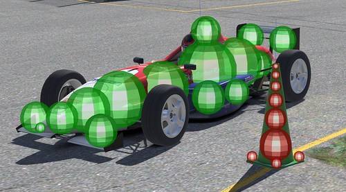
The collision for cars and cones are represented as a series of spheres. This is great in that it is simple and we can efficiently test many spheres against our track geometry. However using spheres makes it hard to represent long, flat or thin shapes or even cones. Also, there would always be holes between spheres, and the final aggregate shape ends up being lumpy, so we need a separate set of planes for the other car/cone.
Testing one set of object spheres against another objects planes works well enough. Unfortunately, it can lead to inconsistencies when the order of the objects is flipped. So, for example, the cone works well when tested against the car planes but not the other way around.
So our problems were that we couldn’t represent our shapes well without using many more spheres and that we needed two different collision representations in use, which led to some problems of asymmetry.
Furthermore, if we can reduce our collision to one representation, then impacts between cars would be more consistent from client to client. This would go some way toward improving what everyone loves to call the netcode.
Also, we have always struggled with the spheres sticking through walls at high speeds, and now cones could get trapped in cars. We wanted to improve in those areas as well.
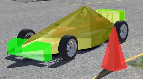
You can see the two different collision representations below.
What Already Works?
Having tried out cones, we knew we needed to make some big changes, so it made sense to take stock of what was currently working well for us.
Simulating physics for iRacing is unique in some ways that differ from typical middleware and aren’t immediately obvious, but they make a significant difference in our pursuit of realism. Anything new would need to maintain these custom features.
Collisions in iRacing are not like the usual billiard ball physics in video games. Typically an impact in a video game is simplified, so it’s considered instantaneous. When one object bounces off another, the response is immediate, and the objects that were moving toward each other will be traveling away from each other with some energy loss.
This works for most games, but it isn’t very realistic in cases we care about. For example, when cars bounce off each other, we want drivers to be able to maintain control realistically. If the impacts affect the cars instantly, it’s hard for players to predict and react in time. Real cars are not infinitely stiff; impacts involve flex which takes a little time.
This is an important phenomenon that iRacing captures by running the physics at a high frequency of 360hz and by implementing what is known as the penalty method for impact forces. Penalty forces by their nature can spread the impact over multiple frames and allow us to model more variety in how materials collide.
Also important to iRacing is the road surface, this needs to be smooth to drive on but also detailed enough that it includes all the real world bumps and dips our laser scans capture.
Most games use a low-resolution triangle mesh for track collision. At iRacing our surfaces are defined parametrically as smooth sweeping road sections on which we overlay a separate bump map. The bump map is what captures all the track details in high fidelity.
This high resolution is critical, so our tire model has enough detail to work with when reproducing an accurate representation of the track features and the road feel.
GJK Collision Shapes
To improve the collision shapes we decided to replace the aging, but efficient spheres and planes approach with a new system which would use sets of convex shapes.
Convex shapes are a good choice because we can still process them efficiently, and by combining a set of them we are able to match the shape of the car very closely.
To support convex shapes, we implemented the GJK algorithm which also makes it trivial to add shapes such as those needed for our tires. The details of the GJK algorithm we can skip and just look at what the new shapes look like.
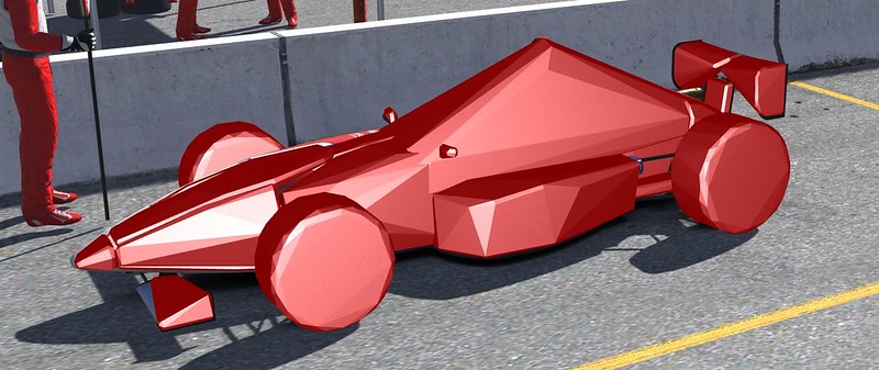
Below is our car with the newly defined GJK shapes.
With the new approach, we can now collide one set of shapes with those of another. So both cars use the same shapes for collision, solving our asymmetry problems and giving us more consistent outcomes.
Another property of the old spheres was that we could move them to represent the effects of damage. Each sphere would move inward to approximate how the car was bending or crushing at that location.
For our convex shapes, we can improve on this as well. We can morph our convex shapes based on damage. In fact, we can control the morphing, so each shape is only affected in the damaged areas, giving us finer control than the spheres.
Modeling these convex shapes has been a huge job for the art team. For each car, they need to reexamine exactly how they are constructed so we can build appropriate shapes. Shapes for the underlying chassis, body panels, wings and everything else need to be modeled, so they fit the car correctly and detach at the right locations. In many cases, we need to go back to reference materials just to figure out exactly how that car was constructed in the real world to match it as closely as possible.
Contact Manifolds
Unfortunately, the physics for contacting convex shapes is not as simple as that of a sphere and a plane.
With our old system, we could reduce each pair of sphere/plane contacts down to a single point for which we would then compute the collision and friction forces.
This was simple, but it did mean that to rest a cone on the ground we needed at least four spheres at the base, one for each corner if it was going to rest realistically rather than roll away. For most objects, this led to us adding yet more spheres.
With convex shapes, on the other hand, we can represent the shape of the cone using only two convex shapes: a box for the base and a pyramid for the top.
But to rest the cone on the ground, we still need to determine the supporting forces concerning how it sits in contact with the road.
Rather than splitting the cone shapes up as we did with our spheres we’d prefer to determine how the base rests on the ground.
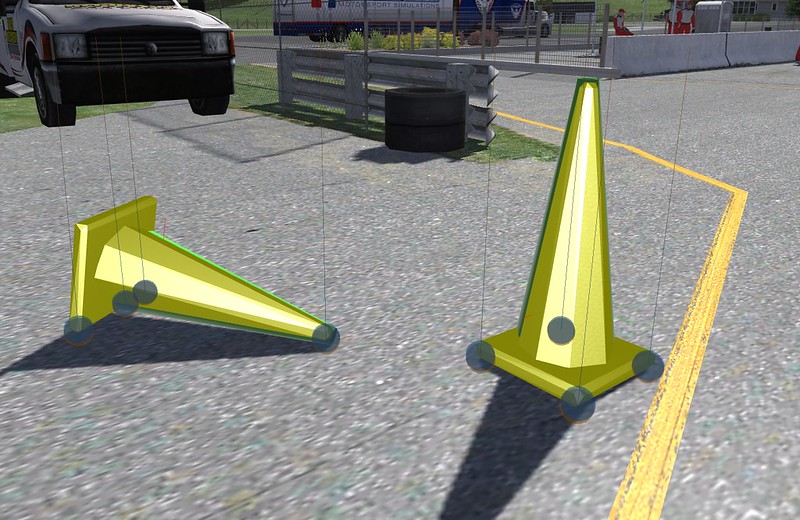
This is solved with what is sometimes called a contact manifold. The manifold maintains a set of contacts collected over the last few frames. Contacts are retained so we can eventually construct a stable set of corner points which will support the cone.
Below is an image showing some cones and their contact manifolds when at rest. The same approach is used for all the important parts of the car as they contact the ground and the surrounding walls, as well as other cars and objects.
Track Collisions
Unfortunately, when it comes to testing against our custom track surface, the new convex shapes are not as straightforward as the spheres.
It was relatively easy to construct planes for each sphere based on the surrounding track data. This was not efficient, but it was workable with the number of spheres we were using for cars. It was also convenient to apply the fine detail from the bump map to the planes.
However, when considering convex shapes, it’s not practical to reduce the track surface to a set of flat planes. Long shapes can potentially stretch across parts of the track that should dip down or rise, and this wouldn’t be captured by flat planes.
As mentioned most games use a low-resolution triangle mesh to represent the environment. This is a more practical representation for GJK shapes, but has its own problems that need to be addressed.
In our case, we need a high level of detail. To reach our required fidelity we need the mesh tessellation to be at least within a half meter. For a track like the Nürburgring that can end up requiring approximately 5 million triangles. Storing that many triangles alone will use almost 100meg.
Fortunately, there are data structures we can use to accelerate mesh collision queries, but those take up even more valuable memory. Our initial attempts ended up with huge data and performance overheads compared to the previous system.
After much head scratching, we were able to design our own custom data structure that was both compact and efficient enough for our high level of detail.
For creating our mesh data, we created a preprocessing tool that reads the parametric track definitions and after much work produces an optimal triangle mesh in our custom format. The tool tries hard to tessellate with consistent precision across the entire road surface while keeping all the featured grooves and transitions our guys work so hard on.
The consistency helps us maintain stable performance no matter what part of the track cars are racing on. With our existing system tight corners or other detailed areas would perform worse due to the extra detail, now we can have the same level of detail in all areas and with the same performance.
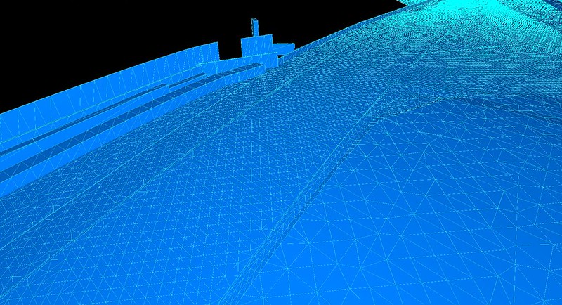
Here is a screenshot of one such track mesh.
Damage Mounts
Colliding with other cars and the environment is only one aspect we need to model. Another important area we need to consider is how we simulate the resulting damage.
As mentioned, for the spheres our old system worked by moving the sphere positions to approximate crushing. The forces for a sphere contact were divided into what we call elastic and plastic forces to model both the collision and damage effects.
Now that we have convex shapes which morph to accurately model crushing we need a complementary method for tracking our damage state.
Additionally, we want to be able to detach some car parts when there is sufficient damage. And in many cases we want those pieces to remain tethered to the car, for example when a hood breaks open but remains hinged and should flap up and down.
This led to the addition of what we call mounts. Each car in addition to having multiple collision shapes now also has a set of mounts associated with each part of the car. Each mount models damage in a local area for that part and can also model a connecting spring to simulate hinges and other attachments.
We position and specify all the mounts needed for damage and attachments across the car. Each mount can be tuned to represent the underlying construction at that location.
As the shapes detect a collision, they generate forces which are propagated through each mount causing appropriate damage. Each contact taken in turn gradually damages the mounts which then cause the collision shape to crush and eventually when possible detach.
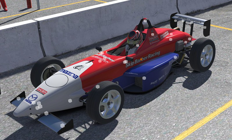
Below you can see an image showing our car with boxes at the mount locations.
Removing Parts
We also need to accurately model the consequences of removing parts. For each part, we need to determine the mass and inertia and how that affects the car as a whole when attached in position or when removed.
At iRacing we have a pretty sophisticated multi-body solver used to calculate how all the connected parts of the car interact given all the external and internal forces acting on the system each simulation step.
The multi-body system is critical to how we model our cars and allows us to build an accurate representation of all the connecting geometry for among other things the suspension, drivetrain, and chassis.
Because the multi-body solver has to do lots of work in real-time our system is designed to precompile optimal code to perform the computations at 360hz. Unfortunately, because we precompile the code, this means the arrangement of bodies needs to be fixed. In other words, we can’t easily disconnect or reconnect bodies from the car.
To remove parts as they break off, we needed to rework this system without sacrificing performance. We were able to do this by augmenting the multi-body system so chassis bodies could maintain removable mass and inertia totals which we dynamically update whenever some part needs to break away or snap on.
After a part detaches we replace it with a new separate part that performs its own collision and physics so it can bounce and tumble down the road independently.
Wheels also need to be removed. Since wheels are already part of the multi-body, we need a similar approach so we can remove their mass.
With all these individual masses now dynamically accounted for we can accurately shed mass and therefore energy during big crashes.
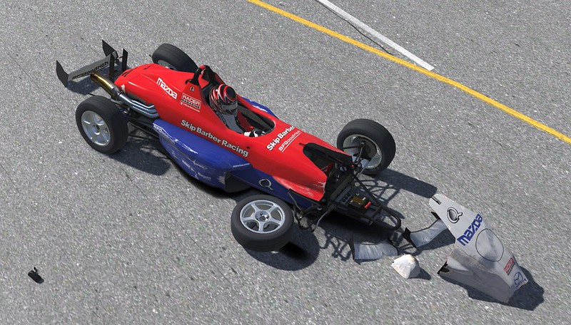
Below is our example car with all parts and a couple of wheels damaged and removed.
Sticky Walls
An unfortunate problem with our old system was that for big impacts the car could end up stuck inside a wall. Despite some clever fixes we were never quite able to solve this completely, and it was another area we wanted to improve.
For the new system, we had the same problems, which stem from the penalty method approach. The penalty method requires that collision shapes are allowed to overlap. The depth of the overlap is then used to determine an appropriate collision force. Unfortunately for soft objects or objects moving very rapidly, this approach starts to break down. If some shapes pass through walls and get over to the wrong side, then the car as a whole will get stuck.
We would see this problem frequently for our new shapes, especially for parts such as body panels and hoods which were thinner than the typical old spheres.
This problem is partly why it is more common for middleware to model collisions as instantaneous. By doing so, they can sidestep the problems caused when shapes overlap for longer times.
We experimented with different methods for solving this tricky problem. Mostly we tried to predict the problem and then revert to instantaneous collision impulses. However, the results were never perfect, and the motion was just not convincing.
This was a challenging problem and one that at times felt like it might never be solved. But in the end, we were able to devise our own unique approach which allows us to maintain the properties we liked from the penalty method while ensuring the collision shapes don’t pass through walls.
Our approach maintains a separate core sphere for each collision shape. A core sphere is small enough to be encapsulated by the corresponding collision shape. Most of the time, these two shapes move in lockstep. However, the core sphere is never allowed to pass through the collision environment.
In the case of a deep collision, the core sphere and the collision shape will separate. The core sphere will remain on or near the surface while the collision shape continues deeper. We are therefore able to maintain an understanding of the surface for that collision shape until it has time to spring back out. This approach allows us to use the penalty method while avoiding the common pitfalls.
Tweaking Properties
Having built our new collision shapes and positioned and connected our damage mounts, we still need to tune all of the associated properties.
Collision shapes have properties defining: mass, material, stiffness, damping, friction, etc. Damage mounts have properties defining: material, yield limits, break limits. And then even more properties for the mount spring behaviors.
All of these properties need to be carefully researched and dialed in for every car. This job fell on our dedicated vehicle dynamics engineers, and it was going to be a huge undertaking.
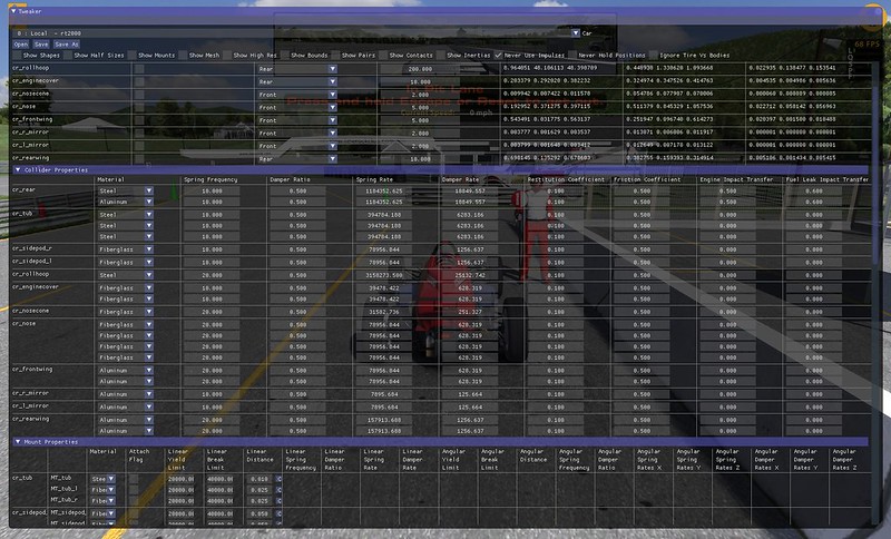
To improve the workflow and accelerate the long process we have developed a live editing interface we call the Tweaker. Using the Tweaker tool, we can adjust all these properties on the car during the simulation as well as inspect things like the collision shapes and mount positions.
The Tweaker is built using the popular Dear ImGui library which allows us to quickly adjust the interface to our needs as the engineers discover new and faster ways to work.
Below is an example showing the Tweaker in use.
Collision/Damage Events
So far we’ve covered what the new collision and damage system is capable of. But we also need to communicate the results to other systems in iRacing.
Rather than add these features as needed, we have a new system for collision and damage events. This system packages all the necessary information for each impact or damage change so it can be parceled off to other areas for processing. We are then able to hook any of our other systems up so they can react appropriately.
We are currently using collision and damage events to improve our particle and sound effects, so they more closely resemble the kind of destruction happening to the car.
Next Steps
When all this new work is finalized, we will be able to start building on our new foundation to add even more improvements.
For example, we’re better placed to improve our simulation step rate to give us even more accurate physics. We should be able to improve how we represent specific curbs and track features when necessary. And ultimately we would like to be able to break cars in half for spectacular Indy 500 crashes.
For now, we need to concentrate on the work still to do. We’ll be busy updating all our cars and all our track objects. We need to update everything in the iRacing service before we can release since there are too many changes for the old and new systems to co-exist.
We’re also still finalizing the new effects and sounds. From there we will need to optimize and debug all these new systems.
That said it’s exciting to reach this point and I’m happy I can share these details.
Thanks
Richard
Official Webpage – www.iRacing.com |
 Bsimracing Sim Racing Resources and News for the racing enthousiast.

